
Design for SLS 3D Printing: Wall Thickness, Tolerance and Orientation Rules for Production Parts
Shubham Garg
Founder & CEO, Autoabode Consumer Electronics Pvt. Ltd. · Autoabode
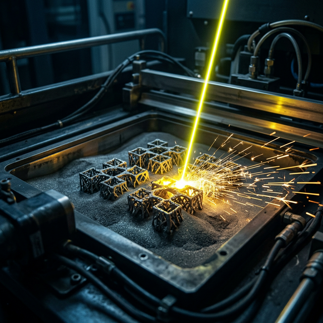
Almost every selective laser sintering part that disappoints an engineering team was already broken before it reached the machine. The powder was in specification, the laser was calibrated, the thermal chamber held its setpoint — and the part still came out warped, out of tolerance, or with a hinge fused solid. The cause sits upstream, in a CAD model built with rules borrowed from FDM, machining or injection moulding. SLS obeys none of them.
This guide is the design-for-SLS reference we give to customers before their first production run. It is organised around the seven decisions that actually determine whether a laser-sintered part is manufacturable at volume: wall thickness, tolerance, orientation, clearance, hole and feature sizing, powder escape, and nesting. Every number below is a working figure from production experience with PA12, PA11 and TPU on the SinterX Pro, the indigenous SLS platform Autoabode builds in New Delhi. Treat them as starting points to be confirmed against your own material and machine calibration, not as universal constants.
Why SLS Design Rules Are Not FDM Design Rules
The defining feature of powder bed fusion is that the unsintered powder around a part is itself the support structure. There is no scaffolding to design around, no support scarring to plan for, no build plate adhesion to worry about. That single fact removes about half the constraints an FDM designer carries — and introduces a different set that catches people out.
What SLS Gives You for Free
- Full geometric freedom — undercuts, internal channels, lattices and organic topology-optimised forms print without supports.
- True isotropy is closer than in FDM: a well-oriented sintered PA12 part typically retains 70–85% of its XY tensile strength in Z, against 30–50% for a comparable FDM part.
- Assemblies can be printed pre-assembled — hinges, captive nuts, chain links and living joints in a single build.
- Nesting in three dimensions, so build cost is driven by packed volume rather than plate area.
What SLS Takes Away
- Powder must physically leave the part. Any sealed internal cavity will stay full of loose powder forever.
- Thermal history varies with position in the cake, so parts in the centre of a dense build cool more slowly than parts at the edge and can shrink differently.
- Surface finish is inherently matte and granular — typically Ra 8–14 µm as-printed — so cosmetic faces need [post-processing](/blog/sls-post-processing-guide-finishing-nylon-parts-india) planned in from the start.
- Sharp internal corners concentrate stress in a semi-crystalline polymer that is notch-sensitive.
A designer who internalises those four constraints will avoid the overwhelming majority of SLS failures. The sections below turn each into a number.
Wall Thickness: The Single Most Common Failure
Minimum wall thickness in SLS is not one number, because a wall's survivability depends on how it is supported by the geometry around it. A 0.8 mm rib bounded on three sides behaves very differently from a 0.8 mm unsupported panel spanning 120 mm.
Working Minimums for PA12
- Absolute process minimum: 0.6 mm — will sinter, but is fragile during depowdering and should be reserved for non-structural detail.
- Recommended structural minimum: 1.0 mm for walls under 40 mm span.
- Large flat panels (over 60 mm span): 2.0–3.0 mm, or 1.2 mm with a ribbed backing structure.
- Load-bearing walls and mounting faces: 2.5–3.0 mm minimum.
- Living hinges in PA12: 0.4–0.6 mm at the hinge line, blended with generous fillets on both sides.
- TPU: add roughly 0.3–0.5 mm to each figure — elastomeric powders sinter with lower green strength and tear more easily during powder removal.
Ribs Beat Thickness
The instinct when a panel flexes is to thicken it. In SLS that is usually the wrong move: doubling wall thickness doubles material cost, doubles the sintered mass that must cool uniformly, and increases warp risk because thick sections shrink more than thin ones. A rib grid is almost always better. Keep ribs at 50–70% of the parent wall thickness to avoid sink-style thermal artefacts, space them at three to five times the wall thickness, and fillet every rib-to-wall junction at a radius of at least 0.5 mm.
The same logic applies to bosses. A solid 12 mm diameter boss will cool slowly and pull the surrounding wall with it. A 12 mm boss cored out to a 3 mm wall and gusseted with four ribs is stiffer per gram and thermally better behaved.
Avoid Abrupt Thickness Transitions
Where a 1 mm wall meets a 4 mm structural section, the two regions shrink at different rates and the boundary becomes a stress riser and a warp initiation site. Blend transitions over a length of at least three times the thickness difference. This one habit eliminates a surprising share of dimensional complaints on large flat parts such as enclosure lids and drone fuselage panels.

Tolerances: What SLS Can and Cannot Hold
SLS is a thermal process, and every thermal process is a shrinkage-management problem. Polyamide powders shrink roughly 3–4% from the CAD dimension as they crystallise. Machines compensate for this with X, Y and Z scale factors calibrated against a benchmark artefact. When those factors are current, the achievable tolerance is predictable. When they drift — typically after a powder batch change or a chamber service — everything gets uniformly slightly wrong, which is the classic signature of a calibration issue rather than a design issue.
Realistic Tolerance Bands
- General dimensions: ±0.3 mm, or ±0.3% of nominal for dimensions above 100 mm — whichever is greater.
- Well-calibrated machine, well-oriented feature, part under 100 mm: ±0.15–0.2 mm is repeatable.
- Z-axis dimensions: consistently the least accurate axis; budget ±0.3 mm even on small parts.
- Hole diameters: print undersized by 0.1–0.3 mm as a rule, because the melt pool grows slightly beyond the scan path.
- Flatness on large panels: expect 0.3–0.5 mm over 200 mm unless the part is ribbed.
Design Around the Tolerance, Not Against It
If a feature genuinely needs H7 fit or better — a bearing seat, a precision optical mount, a sealing face — do not chase it in the sintering process. Print the feature undersized and machine or ream it afterwards, or design in a metal insert. A 3 mm reaming allowance on four bores costs minutes on a bench drill; recalibrating a machine to chase ±0.05 mm on a polymer that moves with humidity does not converge.
Note also that PA12 and PA11 are hygroscopic. A part measured immediately after depowdering and the same part measured after two weeks in Delhi's monsoon humidity will differ measurably. For inspection-critical work, condition parts to a stable humidity before measuring. The material selection guide covers the moisture behaviour of each powder in more depth, and the full range is listed on the SLS materials page.
Orientation: The Decision That Costs Nothing and Changes Everything
Orientation is free at design time and expensive to fix after a failed build. Four properties depend on it: Z-axis strength, dimensional accuracy, surface quality, and build height, which in turn drives build time.
Strength
Layer boundaries remain the weakest plane even in a well-sintered part. Orient so that the primary tensile or bending load runs within the XY plane rather than across layer boundaries. For a bracket that carries a cantilever load, that usually means laying it flat rather than standing it up — the opposite of what packing efficiency would suggest. When a feature such as a thin snap-fit arm must run vertically, thicken it by 20–30% to compensate.
Surface Quality
Downward-facing surfaces in SLS are marginally rougher than upward-facing ones because heat conducts differently into the powder below. Angled surfaces show mild stair-stepping at shallow angles. If a part has one cosmetic face, orient that face upward or at a steep angle, never as a shallow downskin.
Cylindrical Features
A hole printed with its axis vertical (along Z) comes out round. The same hole printed horizontally comes out slightly elliptical and with a sagging upper surface, because the roof of the hole is unsupported melt. If holes must be horizontal, use a teardrop or diamond profile rather than a circle, exactly as one would for FDM, and plan to ream.
Build Height Drives Cost
SLS build time is dominated by the number of layers, not the number of parts. A build 300 mm tall takes roughly three times as long as one 100 mm tall regardless of how full it is. Orienting parts to minimise Z height, then packing the remaining volume with other work, is the core economic lever in powder bed fusion — which is why nesting and orientation should be decided together, not sequentially.
The SinterX Pro is India's first indigenously manufactured SLS 3D printer, running open-material PA12, PA11 and TPU in a thermally controlled chamber sized for production nesting rather than single-part prototyping. Because the material system is open, the shrinkage and scale factors described here are user-adjustable per powder batch instead of locked to a proprietary cartridge — which is what makes tolerance-critical production work practical in-house. See SLS printer options or current pricing in India.
Clearances for Assemblies and Print-in-Place Mechanisms
Printing an assembly pre-assembled is one of SLS's genuine advantages, and the entire trick is clearance. Too tight and the parts fuse into a single solid; too loose and the mechanism rattles. The governing physics is the heat-affected zone: sintering energy spreads slightly beyond the scanned contour, so two surfaces closer than that spread will bond.
- Moving parts — hinges, sliders, rotating joints: 0.4–0.5 mm clearance minimum on every face.
- Interlocking non-moving parts, snap-fits: 0.3 mm.
- Press fits: design 0.1 mm interference and expect to tune per machine.
- Threaded features printed directly: usable from M6 upward with 0.4 mm clearance; below M6, print a plain hole and use a heat-set brass insert or tap it.
- Nested loose parts in a single build (chains, links): 0.5 mm, and confirm powder can reach every interface.
Also confirm that a depowdering path exists for the clearance gap itself. A 0.5 mm gap that is 60 mm deep and open on only one end will hold packed powder that no bead blast will clear.
Powder Escape: The Rule with No Exceptions
Loose powder inside a sealed cavity is trapped permanently. It adds weight, it will eventually shake loose and contaminate a mechanism, and on a flight article it is an unaccounted mass in an unknown location. Every internal void needs at least two escape holes — one to let powder out and one to let air in, otherwise the cavity vapour-locks.
- Minimum escape hole diameter: 4 mm for shallow cavities under 30 mm deep.
- Cavities 30–100 mm deep: 6–8 mm holes.
- Deep or tortuous internal channels: 10 mm and above, plus an access port if the channel turns more than twice.
- Place at least two holes per void, positioned at opposite ends so powder can flow through rather than being scooped out.
- Internal lattices: verify every cell is open to a neighbour. A closed-cell lattice is a powder trap disguised as lightweighting.
If a cavity must be sealed for the final application, print it open and close it afterwards with a plug or adhesive joint. Designing the plug is a five-minute job; recovering a part with 90 grams of trapped powder is not possible.
Nesting and Cost per Part
In SLS, cost per part is essentially a function of packed volume and build height. Understanding this changes how parts are designed, not just how they are arranged.
What Actually Drives Cost
- Build height in Z — the dominant term, since it sets layer count and therefore machine hours.
- Packing density — the fraction of chamber volume occupied by parts, typically 8–15% for awkward geometry and 20–30% for well-designed nestable parts.
- Powder refresh ratio — the proportion of virgin powder blended with reclaimed powder each build, which sets consumable cost.
- Post-processing labour — often underestimated, and directly reducible through design choices such as fewer blind pockets.
Designing for Nestability
Parts that nest well share a few traits: they avoid large enclosed convex volumes, they tolerate being rotated freely, and they are dimensionally modest in at least one axis. If a component can be split into two flatter pieces joined by a bonded or fastened interface, the packing gain is frequently large enough to more than offset the extra assembly step. The economics of this against alternative processes are worked through in the SLS vs FDM cost comparison and in our cost-per-part analysis for low-volume production.
One caution: dense nesting slows cooling in the centre of the cake. For dimensionally critical parts, either reduce packing density or keep the critical parts near the chamber periphery where thermal behaviour is more consistent.
A Pre-Build Design Checklist
Before releasing a model for a production build, walk it against this list. It takes about ten minutes and catches most of what would otherwise be found after the machine has run.
- No wall below 1.0 mm outside deliberate thin-feature detail; no unsupported panel above 60 mm span below 2.0 mm.
- All thickness transitions blended over at least 3× the thickness difference.
- Every internal corner filleted — minimum 0.5 mm, 1.0 mm on load paths.
- Every internal void has two or more escape holes of the correct diameter.
- All moving interfaces at 0.4–0.5 mm clearance; all snap-fits at 0.3 mm.
- Precision fits flagged for post-machining rather than expected from the as-sintered dimension.
- Primary load direction confirmed to lie in the XY plane at the intended orientation.
- Cosmetic faces oriented upward or steeply angled, never as shallow downskins.
- Threads below M6 replaced with plain holes for inserts or tapping.
- Part split or reshaped where doing so materially improves nesting density.
Teams building a repeatable in-house workflow around these rules can review platform options on the SLS printers page, compare against imported systems in the SinterX vs Sinterit comparison, or book a demonstration to run a benchmark part in their own geometry before committing.
Frequently Asked Questions
Q: What is the minimum wall thickness for SLS 3D printing?
A: For PA12 nylon, 1.0 mm is the recommended structural minimum for walls under about 40 mm span, and 2.0–3.0 mm for large unsupported panels above 60 mm. The absolute process minimum is around 0.6 mm, but parts that thin are fragile during depowdering and should be limited to non-structural detail. TPU needs roughly 0.3–0.5 mm more than PA12 in every case because elastomeric powders have lower green strength.
Q: What tolerance can an SLS 3D printer actually hold?
A: Plan for ±0.3 mm or ±0.3% of nominal, whichever is larger. A well-calibrated machine printing a small, well-oriented part can repeat ±0.15–0.2 mm, but the Z axis is consistently the least accurate and should always be budgeted at ±0.3 mm. Anything requiring an H7 fit or better should be printed undersized and reamed or machined rather than chased in the sintering process.
Q: Why do SLS parts need powder escape holes?
A: Unsintered powder is the support material in SLS, so any fully enclosed cavity finishes the build packed solid with loose powder that can never be removed. Two holes per void are needed — one for powder to exit and one for air to enter, or the cavity vapour-locks. Use 4 mm holes for shallow cavities, 6–8 mm for those 30–100 mm deep, and 10 mm or larger for long internal channels.
Q: How does part orientation affect SLS strength?
A: Layer boundaries remain the weakest plane, so a laser-sintered PA12 part typically retains 70–85% of its XY tensile strength when loaded along Z. Orient parts so the primary tensile or bending load runs within the XY plane. Where a thin feature must run vertically, thicken it by 20–30% to compensate. Orientation also determines hole roundness, downskin surface quality and build height, which is the main driver of cost.
Q: Can hinges and moving assemblies be printed in one piece with SLS?
A: Yes — this is one of SLS's real advantages, since no supports are needed inside the mechanism. The requirement is clearance: 0.4–0.5 mm on every face of a moving interface, 0.3 mm for snap-fits and interlocking static parts. Confirm that loose powder has a path out of the clearance gap itself; a narrow gap that is deep and open at only one end will trap powder that cannot be blasted clear.
Frequently Asked Questions
For PA12 nylon, 1.0 mm is the recommended structural minimum for walls under about 40 mm span, and 2.0–3.0 mm for large unsupported panels above 60 mm. The absolute process minimum is around 0.6 mm, but parts that thin are fragile during depowdering and should be limited to non-structural detail. TPU needs roughly 0.3–0.5 mm more than PA12 in every case because elastomeric powders have lower green strength.
Shubham Garg
Founder & CEO, Autoabode Consumer Electronics Pvt. Ltd. · Autoabode Consumer Electronics Pvt. Ltd.
Expert author at Autoabode — writing at the intersection of industrial 3D printing, defence manufacturing, and advanced UAV systems. Based in New Delhi, India.
Explore Autoabode's Platforms
This article is part of Autoabode's technical journal. Learn more about our core platforms built in India for defence, aerospace, medical and industrial teams:
More from the Journal
Off-Grid Communication Solutions for Mountainous Terrain: An Engineering Field Guide for India's High-Altitude Operators
Off-grid communication solutions for mountainous terrain are not optional in India — they are the difference between a coordinated operation and a stranded section. This engineering field guide breaks down the radio physics that defeats conventional VHF/UHF in the Himalayas, the mesh architectures that survive ridge-line shadowing, and the cold-weather, power-budget and security trade-offs that determine whether a system delivers in the Karakoram and Western Ghats. Built around real deployment data from Autoabode's MeshVani encrypted communicator and MeshVani Relay platform in service with the Indian Army, ITBP, NDRF and high-altitude expedition teams.
Drones & UAV · 7 min readModular UAV Payloads for Multi-Role Missions: A Technical Guide
Explore the technical specifications and strategic advantages of modular UAV payloads for multi-role missions. This guide covers hot-swap systems, sensor fusion, and real-world applications for defense and industry.